
The CNC E80 Series boasts drastic improvements in performance and a higher accuracy than ever before. The simple and easy-to-use E80 Series helps in achieving a greater cost performance, and fits best with simple machine configurations.
– The Mitsubishi Electric CNC Engineering Team

High performance & accuracy
![]()
Models for various machine configurations TypeA/TypeB
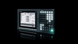
Leading design Display Units and Keyboards
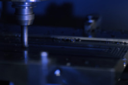
With Mitsubishi Electric’s high-speed CNC-dedicated CPU, the E80 Series reduces cycle times due to a higher program and PLC processing capability. Higher optical communication speeds between the CNC and drive acheive higher accuracy in machining.
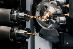
TypeA and TypeB models are available for both machining centers and lathes. Select the model with the specifications that suit the machine configuration best. [Machining center system] TypeB supports machines with up to 3 axes. TypeA supports the setup of a rotary table. [Lathe system] TypeB controls 3 feed axes and 2 spindles as standard. Select TypeA for configurations that have a maximum of 3 spindles such as compound lathes.
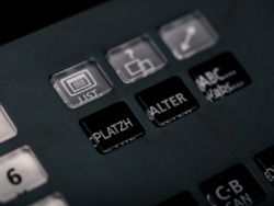
The E80 Series adopts the M800/M80 Series design. The display unit and keyboard are only 9.5 mm thick, and opens up new possibilities for machine design. There are 2 types of keyboard layouts, one for lathes and the other for milling.
 The E80 Series comes with enhanced high-accuracy control functions for lathes with milling functions as standard. Functions such as the interactive cycle insertion function make programming easier, improving operability.
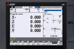 The simple monitor screen puts all the essential information for mass production on one screen, making it simple to find information immediately. Information such as the selected tool and the remaining lifetime can be checked by viewing the tool icon.
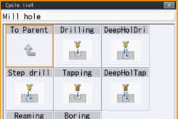 The E80 Series comes with Interactive Cycle Insertion (ICI). This simple programming system lets you easily create programs for each process. Whether you need to turn, copy, groove or thread, the easy-to-read interface clearly displays the tool path or machining shape you want.
 Synchronous tapping can be performed with an analog-connected spindle such as an inverter without using a dedicated tool holder. The applicability to a wide array of machine specifications allows for more efficient machining.
E80 Series high-accuracy control minimizes deviation of the actual tool path from the command path, improving the accuracy of the machining of corners and arcs.
 The same machining program can be used when the workpiece coordinate system does not match the actual workpiece coordinate system, or when the actual workpiece length is different. This function helps to create machining programs easier.
 Flexible commands allow the user to switch between diameter/radius designation for each axis with the G-code at any time. Flexible commands are particularly useful for programs where turning and milling coexist.
The finished shape is displayed in 3D while creating a machining program. Checking the finished shape in real-time during program creation allows the user to correct mistakes as they appear in the finished shape.
Check the machining program while viewing the actual operation of the machine. Also, forward run/reverse run operation can be checked meticulously at a desired feedrate (manual handle feed) , making prototype checks more accurate and easier than before.
3D solid program check allows the user to check a finalized machining program against the 3D graphic of the final shape for the program. Being able to perform a detailed check of the final shape before production on the actual machine is a major advantage.
| Lathe system | Machining center system | |||
|---|---|---|---|---|
| TypeA | TypeB | TypeA | TypeB | |
| Max. number of axes (NC axes + Spindles + PLC axes) | 8 | 5 | 6 | 4 |
| Max. number of NC axes (in total for all part systems) | 5 | 4 | 5(*1) | 3 |
| Max. number of spindles | 3 | 2 | 1 | 1 |
| Max. number of PLC axes | 3 | 3 | 2 | 0 |
| Number of simultaneous contouring control axes | 4 | 4 | 4 | 3 |
| Max. number of part systems | ◯1 | ◯1 | ◯1 | ◯1 |
| Display unit-side High-speed program server mode | ◯ | ◯ | ◯ | ◯ |
| Front-side SD card mode | ◯ | ◯ | ◯ | ◯ |
| Least command increment | 0.1μm | 0.1μm | 0.1μm | 0.1μm |
| Least control increment | 1nm | 1nm | 1nm | 1nm |
| Program memory capacity (number of programs stored) | 230KB [600m] (400 programs) | 230KB [600m] (400 programs) | 500KB [1280m] (1000programs) | 500KB [1280m] (1000programs) |
| Max. number of tool offset sets | 99 sets | 99 sets | 200 sets | 99 sets |
| Built-in PLC capacity [number of steps] | ◯20000 | ◯20000 | ◯20000 | ◯20000 |
| Multi-program [number of programs] | ◯60 | ◯60 | ◯60 | ◯60 |
| Multi-project [number of projects stored] | ◯1 | ◯1 | ◯1 | ◯1 |
| Macro program Variable command | 600 sets | 200 sets | 600 sets | 200 sets |
| Machine tool builder macro | ◯ | ◯ | ◯ | ◯ |
| Workpiece coordinate system shift | ◯ | ◯ | - | - |
| 3D solid program check | ◯ | ◯ | ◯ | ◯ |
| Manual arbitrary reverse run (program check operation) | ◯ | ◯ | - | - |
| Interactive cycle insertion | ◯ | ◯ | ◯ | ◯ |
| Diameter/Radius designation switch | ◯ | ◯ | - | - |
| Synchronous tapping with analog I/F spindle | ◯ | ◯ | ◯ | ◯ |
| Workpiece position measurement | - | - | ◯ | ◯ |
| Simple inclined surface machining command | - | - | ◯ | - |
| High-accuracy control (G61.1/G08) | ◯ | ◯ | ◯ | - |
| eSSS control | ◯ | ◯ | ◯ | - |
| Tolerance control | ◯ | ◯ | ◯ | - |
| OMR-FF | ◯ | ◯ | ◯ | ◯ |
| Spindle-mode servo motor control | ◯ | ◯ | - | - |
| Finish shape view programming | ◯ | ◯ | - | - |
| Email notification to operator | ◯ | ◯ | ◯ | ◯ |
| Operation history (detailed alarm history information) | ◯ | ◯ | ◯ | ◯ |
| CC-Link (Master/Local) | □ | □ | □ | □ |
| PROFIBUS-DP (Master) | □ | □ | □ | □ |
| EtherNet/IP | □ | □ | □ | □ |
| MES interface library | ◯ | ◯ | ◯ | ◯ |
| EcoMonitorLight connection | ◯ | ◯ | ◯ | ◯ |
| System lock | ◯ | ◯ | ◯ | ◯ |
This manual is a guide for using the MITSUBISHI CNC.
This manual covers the items required for maintaining the MITSUBISHI CNC M800/M80/E80 Series.
This manual is a guide for using the MITSUBISHI CNC M800/M80/E80 Series.
This manual explains the PLC development environment.
Manuals related to M800/M80/E80/C80 Series are listed as follows.
M800-M80-E80-C80 Series HAND BOOK
This manual describes the various signal interfaces and functions of the NC unit required when creating Mitsubishi Electric CNC sequence programs (built-in PLC).
This manual describes how to carry out Mitsubishi Electric CNC programming.
This manual describes how to carry out Mitsubishi Electric CNC programming.
This manual describes the specifications of Mitsubishi Electric CNC.
This manual describes the specifications of Mitsubishi Electric CNC.
This manual covers the items required for installing, connecting and setting up the MITSUBISHI CNC.
Fields marked with a * are mandatory.
Mitsubishi Electric Europe B.V.
German Branch
Mitsubishi-Electric-Platz 1
D - 40882 Ratingen
Tel.: +49 (0)2102 / 486 - 0
Fax: +49 (0)2102 / 486 - 1120
cnc.sales@meg.mee.com

Benjamin Buzga
CNC Sales & Business Development Manager