
The M800VS makes high performance and high speed possible by using a multi-CPU architecture and the Mitsubishi Electric OS.
– The Mitsubishi Electric CNC Engineering Team
![]()
High-precision machining centers

Multi-axis/multi-part system control

Simultaneous 5-axis interpolation control
Leading the way in today’s industrial globalization, the innovative products of Mitsubishi Electric continue to exceed the expectations of users around the world. The outstanding performance of our CNC lineup consistently wins praise from users for their high levels of productivity, intuitive usability, and superior functionality. However, to develop the M800/M80 Series, we went back to the drawing board and completely reexamined our cutting-edge control technologies. The result is a breakthrough in the control of high-speed, high-precision machining.
The Pursuit of a dedicated CNC CPU began with design validation on an unprecedented scale as well as high-precision simulations to verify processing performance. Achieving a leap in processing performance demanded the integration of innovative technologies beyond optimizing processor manufacturing processes. Overcoming numerous hurdles and maximizing the potential of the processor, we succeeded in producing a CNC-dedicated CPU that achieves unprecedented high-speed processing performance.
The story of the M800/M80 Series began with conventional development to produce incremental evolutionary improvements. But our goal was a revolutionary leap in CNC performance. Our project team determined that the only way to significantly boost processing performance and totally satisfy user demands would be the creation of a CPU optimized for CNC control. This insight inspired Mitsubishi Electric’s first-ever attempt to develop a CNC-dedicated CPU and opened a new chapter in CNC development.
![]() OMR-CC – Optimum machine response-contour control – reduces the cycle time without compromsing the accuracy. Therefore the control processing adjusts to the workpiece shape and corrects position error.
OMR-CC – Optimum machine response-contour control – reduces the cycle time without compromsing the accuracy. Therefore the control processing adjusts to the workpiece shape and corrects position error.
 NC control unit with built-in wireless LAN and screen mirroring function allows you to operate NCs without constraints of time and place. For an efficiency and smarter manufacturing.
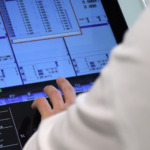 Developing a machining program and setting up values by simply following a guidance.
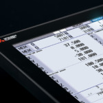 The display and keyboard have been redesigned. Measuring only 9.5mm thick (excluding protrusions), the possibilities of machine tool design have been expanded. In addition, their gray-scale colors can be easily harmonized with machines in different colors.The surfaces of display and keyboard are ush, providing beauty and usability as well as increased operability. 10.4-type and larger displays have touchscreen made of beautiful, long-life glass, which allows you easy day-to-day maintenance. Vertical mount and horizontal mount keyboards are included in the product line.
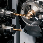 Milling features and multi-axis, multi-part system control features have been significantly improved. Progress has been made in operability, enabling operators to implement ever more complex machining in an easy and efficient manner.
 M800V/M80V Series offers SSS 4th-generation (SSS-4G) control, enabling high-speed, high-accuracy, high-quality machining. SSS-4G control provides features that are effective in reducing tact time, including optimal acceleration/deceleration suited to each axis’ characteristics. In addition, SSS-4G is capable of reducing machine vibration during high-speed cutting.
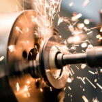 Chatter suppression function increases lathe machining accuracy by automtically detecting by connecting an accelerometer to the RT processing unit. Chatter is suppressed by adjusting the spindle speed, achieving high-accuracy high-quality machining.
The data collected from MTConnect compatible device can be imported into Edgecross and used for edge applications etc. MTConnect is an open protocol for machine tools. By using the MTConnect Adapter which is compatible with MITSUBISHI CNC M800 / M80 Series and M700/M70 Series, you can easily collect and utilize various data of the machine tool which works with MITSUBISHI CNC.
A software that collects operation data and PLC device data from controllers of CNC machine tools and provides the collected data to host IT systems, industrial platforms for edge computing, edge applications etc.
The NC screens can be displayed on an external PC/tablet PC. Operator can monitor the machine tool’s status and operate the NC screen without going to the factory floor, which helps to improve the operation efficiency. (The function is enabled on a non-Windows-based NC display. No external computer is required.)
I/O units have been redesigned. The renewed I/O communication method makes it possible to significantly increase the maximum number of contact points per channel, enabling a number of peripheral equipment and devices to be controlled by CNC alone.
Built-in PLC functionality for I/O control has been improved. This CNC supports Multi-project PLC, a feature that enables ladder logics for peripheral equipment to be managed separately from those for machine tools. This creates a more efficient environment for operators working together in developing and managing ladder logics.
M800/M80 Series has a feature called Machine Group-based Alarm Stop, which stops operation of individual machine groups if an alarm occurs when control is combined with the MDS-E/EM/EJ Series. This feature allows continuation of machining even when an alarm occurs on a loader, magazine or other peripheral equipment.
Lathe features and multi-axis, multi-part system control features have been significantly improved. Progress has been made in operability, enabling operators to implement ever more complex machining in an easy and efficient manner.
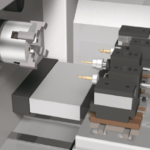
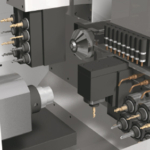
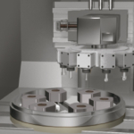
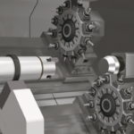
SSS control has further evolved, realizing high-speed, high-accuracy, high-quality machining. In addition, this CNC offers features that bring out the full potential of each axis and minimize non-cutting time, leading to higher productivity
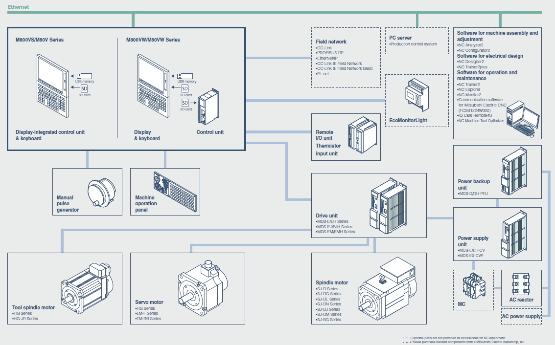
A wide selection of fieldbus networks supports the integration of in factory automation systems. Compatible MES interface function that allows the automatic transmission of from CNC data, such as quantities or maintenance-relevant data to a production control system. This supports the efficient integration into production or Quality control systems.
The I/O modules were newly developed. The modules can DIN rails and have been designed for improved I/O control extended by built-in PLC functionality. Software tools at the highest level support you in the design process to the commissioning of machine tools. Simplify your design and machine manufacturing processes.
M800V/M80V Series provides a range of safety features collectively called the Smart Safety Observation Function. This function has achieved full conformity with the safety standards that cover the entire system including CNC, drive, I/O, sensors and communication.
Refer to the specifications manuals for details. (*1) G/B:Guide Bush (*2) The 8.4-type display unit is incompatible. (*3) Windows-based display unit/Windows-less display unit (*4) Limited to the simultaneous 4-axis contouring control.
| M800VS Series | M80V Series | |||
|---|---|---|---|---|
| M850VS | M830VS | Type A | Type B | |
| Max. number of axes (NC axes + Spindles + PLC axes) | ◯16 △32 | ◯16 △32 | 13 | 9 |
| Max. number of NC axes (in total for all part systems) | ◯16 △32 | ◯16 △32 | 10 | 7 |
| Max. number of spindles | 8 | 8 | 6 | 4 |
| Max. number of PLC axes | 8 | 8 | 6 | 6 |
| Number of simultaneous contouring control axes | 8 | 4 | 4 | 4 |
| Max. number of NC axes in a part system | ◯8 △ 12 | ◯8 △ 12 | 8 | 5 |
| Max. number of part systems (main+sub) | ◯ 4 △ 8 | ◯ 4 △ 8 | ◯ 4 | ◯ 2 |
| Max. number of main part systems | ◯ 4 △ 8 | ◯4 △ 8 | ◯ 2 | ◯ 2 |
| Max. number of sub part systems | ◯ 4 △ 8 | ◯4 △ 8 | ◯ 2 | ◯ 1 |
| Display unit-side High-speed program server mode | △ | △ | ◯ | ◯ |
| Least command increment | ◯ 0,1 µm △ 1 nm | ◯ 0,1 µm △ 1 nm | ◯ 0,1 µm | ◯ 0,1 µm |
| Least control increment | ◯ 1 nm | ◯ 1 nm | ◯ 1 nm | ◯ 1 nm |
| Max. number of tool offset sets | ◯ 128 sets △ 999 sets | ◯ 128 sets △ 999 sets | ◯ 256 sets | ◯ 99 sets |
| Built-in PLC capacity | ◯ 128 000 △ 512 000 | ◯ 128 000 △ 512 000 | ◯ 64 000 | ◯ 32 000 |
| Multi-project [number of projects stored] | ◯ 2 △ 6 | ◯ 2 △ 6 | ◯ 3 | ◯ 2 |
| Data protection by user's level | △ | △ | ◯ | ◯ |
| Workpiece coordinate system shift | ◯ | ◯ | ◯ | ◯ |
| 3D solid program check | ◯ | ◯ | ◯ | ◯ |
| Interactive cycle insertion | △ | △ | ◯ | ◯ |
| Multiple spindle synchronization set control | ◯ | ◯ | ◯ | ◯ |
| Spindle superimposition control | △ | △ | ◯ | – |
| High-accuracy control | △ | △ | ◯ | ◯ |
| High-speed high-accuracy control II (G05P10000) max.[kBPM] | △ 168 | △ 168 | ◯ 67.5 | – |
| SSS control | △ | △ | ◯ | ◯ |
| Tolerance control | △ | △ | ◯ | ◯ |
| OMR-FF | △ | △ | ◯ | ◯ |
| OMR-CC (Optimum Machine Response - Contour Control) | △ | △ | ◯ | ◯ |
| Rapid traverse block overlap | △ | △ | ◯ | ◯ |
| Spindle-mode servo motor control | △ | △ | ◯ | ◯ |
| Real-time tuning 1 (speed gain) | △ | △ | ◯ | – |
| Real-time tuning 2 (rapid traverse time constant) | △ | △ | ◯ | – |
| Inclined surface machining command | △ | △ | ◯ | – |
| 3-dimensional manual feed | △ | △ | ◯ | – |
| Finish shape view programming | △ | △ | ◯ | ◯ |
| VNC server | △ | △ | ◯ | ◯ |
| CC-Link (Master/Local) | □ | □ | □ | □ |
| PROFIBUS-DP (Master) | □ | □ | □ | □ |
| CC-Link IE Field (Master/Local) | □ | □ | □ | □ |
| EtherNet/IP | □ | □ | □ | □ |
| MES interface library | △ | △ | ◯ | ◯ |
| Machine group-based alarm stop | △ | △ | ◯ | ◯ |
Refer to the specifications manuals for details. (*1) G/B:Guide Bush (*2) The 8.4-type display unit is incompatible. (*3) Windows-based display unit/Windows-less display unit (*4) Limited to the simultaneous 4-axis contouring control.
| M800VS Series | M80V Series | |||
|---|---|---|---|---|
| M850VS | M830VS | Type A | Type B | |
| Max. number of axes (NC axes + Spindles + PLC axes) | ◯ 16 △ 32 | ◯ 16 △ 32 | 11 | 9 |
| Max. number of NC axes (in total for all part systems) | ◯16 | ◯16 | 9 | 5 |
| Max. number of spindles | 6 | 6 | 4 | 2 |
| Max. number of PLC axes | 8 | 8 | 6 | 6 |
| Number of simultaneous contouring control axes | 8 | 4 | 4 | 4 |
| Max. number of NC axes in a part system | ◯ 8 △ 12 | ◯ 8 △ 12 | 8 | 5 |
| Max. number of part systems (main+sub) | ◯ 2 | ◯ 2 | ◯ 2 | ◯1 |
| Max. number of main part systems | ◯ 2 | ◯ 2 | ◯2 | ◯1 |
| Max. number of sub part systems | ◯ 2 | ◯ 2 | – | – |
| Display unit-side High-speed program server mode | △ | △ | ◯ | ◯ |
| Least command increment | ◯ 0,1 µm △ 1 nm | ◯ 0,1 µm △ 1 nm | ◯ 0,1 µm | ◯ 0,1 µm |
| Least control increment | △ 1 nm | △ 1 nm | △ 1 nm | △ 1 nm |
| Max. number of tool offset sets | ◯ 200 sets △ 999 sets | ◯ 200 sets △ 999 sets | ◯ 400 sets | ◯ 400 sets |
| Built-in PLC capacity | ◯ 128 000 △ 512 000 | ◯ 128 000 △ 512 000 | ◯ 64 000 | ◯ 32 000 |
| Multi-project [number of projects stored] | ◯ 2 △ 6 | ◯ 2 △ 6 | ◯ 3 | ◯ 1 |
| Data protection by user's level | △ | △ | ◯ | ◯ |
| 3D solid program check | ◯ | ◯ | ◯ | ◯ |
| Interactive cycle insertion | △ | △ | ◯ | ◯ |
| High-accuracy control | △ | △ | ◯ | ◯ |
| High-speed high-accuracy control II (G05P10000) max.[kBPM] | △ 168 | △ 168 | ◯ 101 | ◯ 101 |
| High-speed high-accuracy control III (G05P20000) max. [kBPM] | △ 540 | △ 540 | ◯ 202 | – |
| SSS control | △ | △ | ◯ | ◯ |
| Tolerance control | △ | △ | ◯ | ◯ |
| Variable-acceleration pre-interpolation acceleration/deceleration | △ | △ | – | – |
| OMR-FF | △ | △ | ◯ | ◯ |
| OMR-CC (Optimum Machine Response - Contour Control) | △ | △ | ◯ | ◯ |
| Rapid traverse block overlap | △ | △ | ◯ | ◯ |
| Spindle-mode servo motor control | △ | △ | ◯ | ◯ |
| Real-time tuning 1 (speed gain) | △ | △ | ◯ | – |
| Real-time tuning 2 (rapid traverse time constant) | △ | △ | ◯ | – |
| Tool center point control | △ | △(*2) | ◯(*2) | – |
| Inclined surface machining command | △ | △ | ◯ | – |
| 3-dimensional manual feed | △ | △ | ◯ | – |
| Finish shape view programming | △ | △ | ◯ | ◯ |
| VNC server | △ | △ | ◯ | ◯ |
| CC-Link (Master/Local) | □ | □ | □ | □ |
| PROFIBUS-DP (Master) | □ | □ | □ | □ |
| CC-Link IE Field (Master/Local) | □ | □ | □ | □ |
| EtherNet/IP | □ | □ | □ | □ |
| MES interface library | △ | △ | ◯ | ◯ |
| Machine group-based alarm stop | △ | △ | ◯ | ◯ |
This manual covers the items required for installing, connecting and setting up the MITSUBISHI CNC.
This manual describes the specifications of Mitsubishi Electric CNC.
This manual describes the specifications of Mitsubishi Electric CNC.
This manual is a guide for using the MITSUBISHI CNC 800V/80V Series. Programming is described in this manual, so read this manual thoroughly before starting programming.
This manual is a guide for using the MITSUBISHI CNC 800V/80V Series. Programming is described in this manual, so read this manual thoroughly before starting programming.
This manual describes the various signal interfaces and functions required when creating MITSUBISHI CNC M800V/M80V/E80 Series sequence programs (built-in PLC). Read this manual thoroughly before programming. Thoroughly study the "Safety Precautions" on the following page to ensure safe use of this NC unit.
These specifications are the programming manual used when creating the sequence program with the PLC development software, or Mitsubishi Electric Co.'s integrated FA software MELSOFT series (GX Developer).
This manual is a guide for using the MITSUBISHI CNC.
This manual is referred to when using the MITSUBISHI CNC M800V/M80V Series. This manual explains how to operate, run and set up this NC unit. Read this manual thoroughly before using the NC unit.
This manual covers the items required for maintaining the MITSUBISHI CNC M800V/M80V/E80 Series.
This manual explains the PLC development environment.
Fields marked with a * are mandatory.
Mitsubishi Electric Europe B.V.
German Branch.
Mitsubishi-Electric-Platz 1
D - 40882 Ratingen
Tel.: +49 (0)2102 / 486 - 0
Fax: +49 (0)2102 / 486 - 1120
cnc.sales@meg.mee.com

Benjamin Buzga
CNC Sales & Business Development Manager